Welding Lobe Diagram

Comparison Of Weld Lobe Diagram Between The Traditional Rsw And Ma

The Weld Current Vs Weld Time Diagram Weld Lobe Download

Schematic Diagram Illustrating The Acceptable Welding Range Weld

Weld Lobe Diagrams For Z 0 Z 10 And Z 20 Specimens T M M D

The Lobe Curve For The Resistance Spot Welding Of Trip1100 Steel

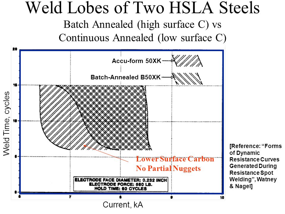
Weld Lobes Of The Three Steels At An Electrode Force Of 3 6 Kn
Experience gained from user contact and welding training of crewmembers showed that.
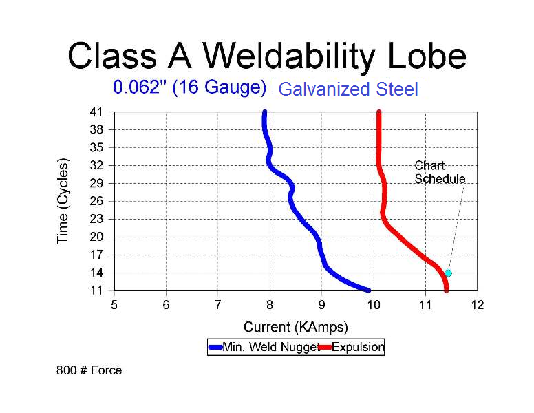
Welding lobe diagram. Welding is the process of joining two similar metals and it is applicable in most of the field like construction of bridges huge buildings railways roadways automotive and aircraft construction pipe lines tanks and vessels machinery parts. This article deals with the classification of welding methods depending on the state of the material during welding. The weld lobe in spot welding provides an indication of good quality joining and the tolerance of the weld schedule in production stage. Under certain conditions a larger lobe can be achieved using 2 pulse weld current input over 1 pulse and 3 pulse inputs.
1 weld lob is to find the best or suitable welding condition for given combination of sheets. A weld lobe diagram is a two dimension graphical representation of ranges of welding parameters for a specific material and its thickness to compare an. Welding lobe could be widened with the use of optimized welding parameters. Standard procedures that can be followed to develop spot weld lobes are found in.
The weld lobe in spot welding provides an indication of good quality joining and the tolerance of the weld schedule in production stage. Plastic or pressure welding. A robust weld lobe diagram delimits a volume in 3d an area in 2d within which all values of force current and time have good probability of giving acceptable results. Welding technique used for joining metallic parts usually through the application of heat this technique was discovered during efforts to manipulate iron into useful shapes.
In this study trip800 steel was used for the experiments and welding times of 5 10 15 20 and 25 cycles were selected with welding currents ranging from 1 to 7 ka with an interval of 2 ka and from 7 to 10 ka with an interval of 1 ka. Welded blades were developed in the 1st millennium ce the most famous being those produced by arab armourers at damascus syria the process of carburization of iron to produce hard steel was known at this time but the. The weld lobe diagram was also used to examine the. 10 and han et al.
Titanium coated electrodes can further increase the width of the welding lobe allowing an increased range of operating currents during welding. This is a very important concept to eliminate all expulsion. In this study trip800 steel was used for the experiments. Weldability lobe diagram is one of the most powerful techniques that can be used to il lustrate the effects of welding current and time.

1 D Welding Lobe Showing The Nugget Diameter Growth In Relation To

Example Of A Current Time Welding Lobe Download Scientific Diagram

Lobe Curves Of Resistance Spot Welds For Sts430 Sts430 And

Weldability Lobe Of Dp590 Steel Sheet Of 1 Mm Thickness P1 And P2

Estimation Of Lobe Curve With Material Strength In Resistance

Spot Welding An Overview Sciencedirect Topics
B Weld Lobe Of 1 2mm Base Metals Download Scientific Diagram

Shows The Welding Current And Voltage Signal Corresponding To

Lobe Curve Del 4 Mm T 0 8 Mm Lap Joint Download Scientific

Weldability Lobe According To Iso 14327 2004 E Download
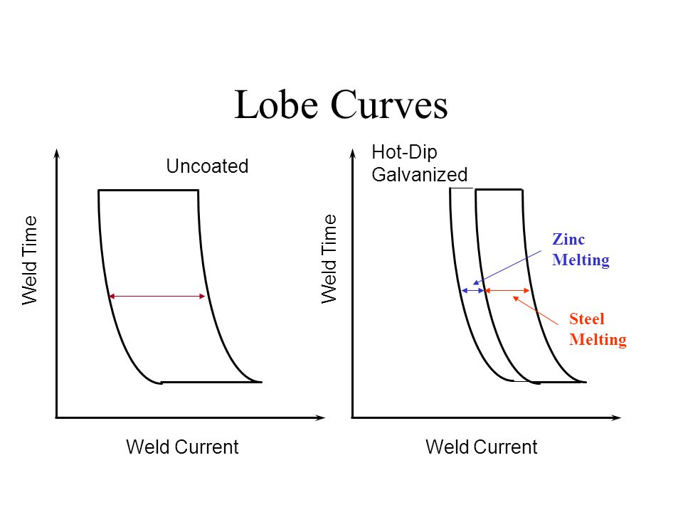
Coated Steel Weldability Resistance Welding Lesson Objectives
What Is A Weld Lob And Why Is It Important In A Weld Shop Biw
Uncoated Plain Carbon Steel Material Variables Uncoated Plain