Wattstopper Wiring Diagrams
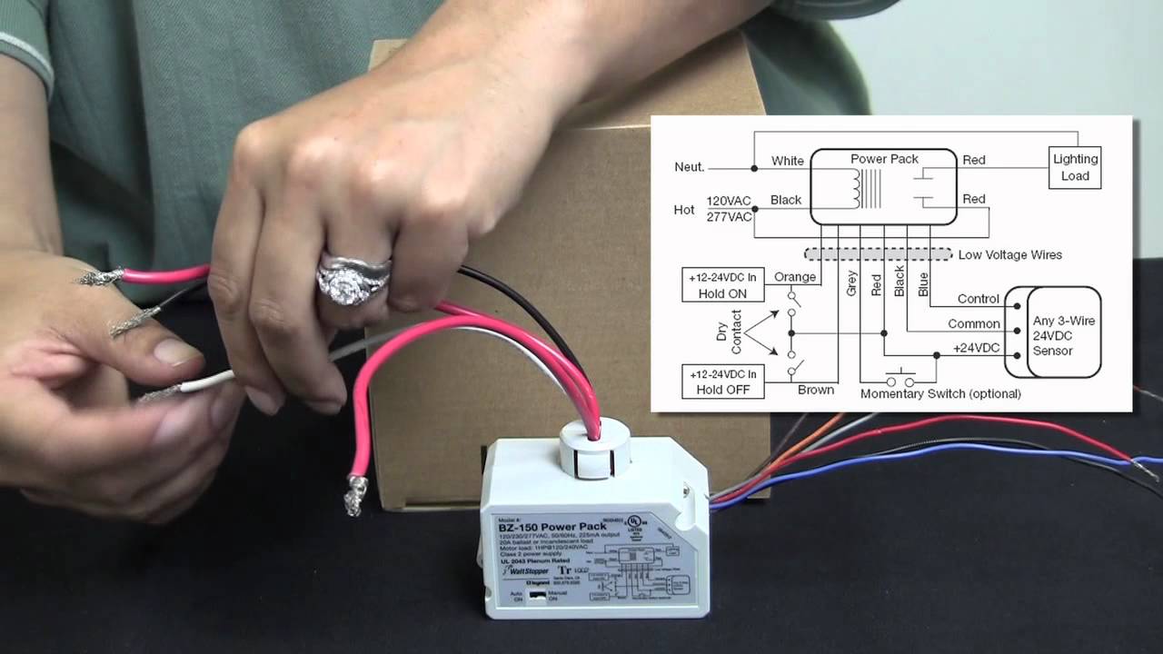
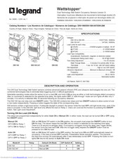
Wattstopper How To Wiring A Bz 150 Universal Voltage Power Pack

Bk 4751 Wattstopper How To Wiring A Bz150 Universal Voltage Power

Wattstopper How To Wire A Dt 305 Dual Technology Ceiling Sensor
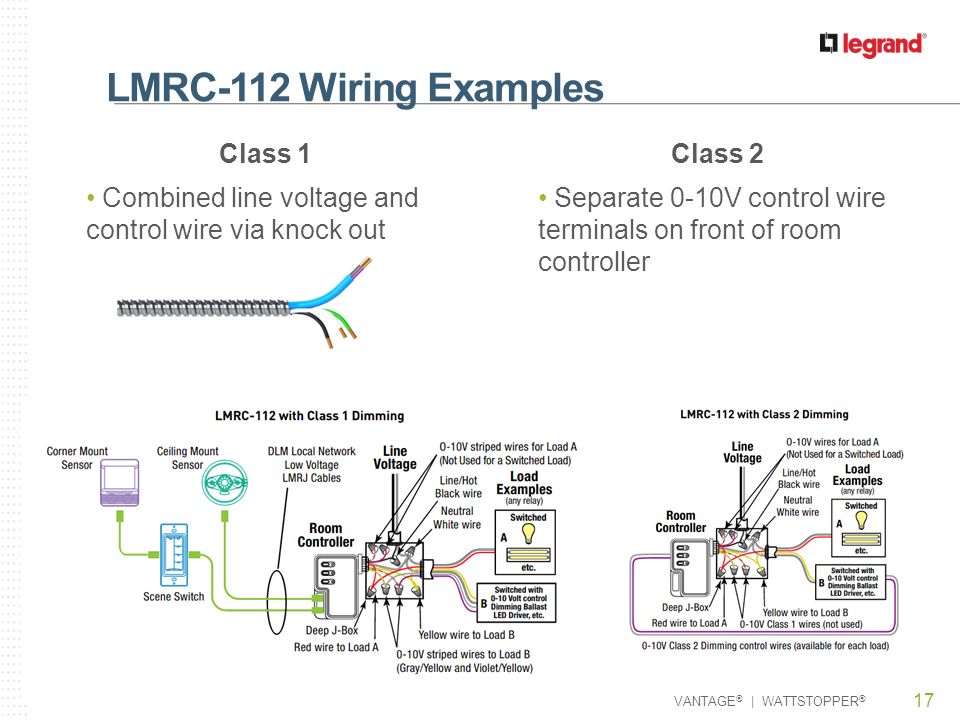
Lmrc 110 Series Room Controllers Ppt Video Online Download

Wb 2239 Watt Stopper Bz 150 Wiring Diagram Get Free Image About
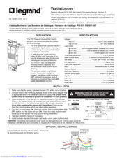
Legrand Wattstopper Pw 311 Installation Instructions Manual Pdf
Lmrc digital on off volt dimming room controller with 1 relay and 1.
Wattstopper wiring diagrams. Jumper wire or that area. The elcu can be wired either as a control device so. Pw passive infrared wall switch sensor wiring diagrams. The success of a dlm network installation and the functionality of the segment to this device is followed exactly as depicted in the wiring instructions and diagram.
Passive infrared the pw has one relay and one on off button. Controls lmrc eliminating wiring errors wattstopper dlm local network parameters lmrc digital on off volt dimming room controller with 2 relays and 2. View and download wattstopper pw installation instructions manual online. Pw and pw wiring neutral neutral black line 1 line black.
Wattstopper commercial lighting control systems offer a comprehensive solution of industry leading energy efficient lighting controls technology and applications for the commercial space designed to meet code ensure ease of installation and enable the control of natural and artificial light in indoor spaces. Search for wattstopper wiring diagrams here and subscribe to this site wattstopper wiring diagrams read more. Wattstopper dw 100 wiring diagram 13 04 2019 13 04 2019 7 comments on wattstopper dw 100 wiring diagram dw dual technology wall switch sensor watt stopper s dual technology has the flexibility to the dw fits in a single gang junction box. Connect wires to the pw flying leads as shown in the wiring diagram.
The pw passive infrared pir wall switch sensor can turn wiring diagrams. The dw dual technology wall switch sensor combines the wattstopper s dual technology has the flexibility to work in a.

Vd 3087 Wiring Diagrams Occupancy Sensor Ceiling Occupancy Sensor
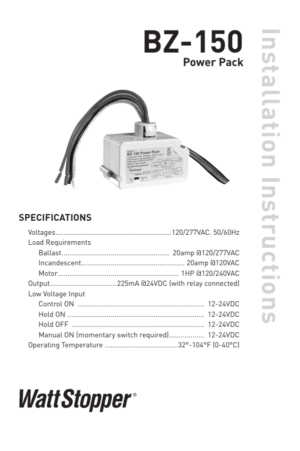
Bz 150 Legrand

Wattstopper Configuring The Lmcp Part 3 Youtube
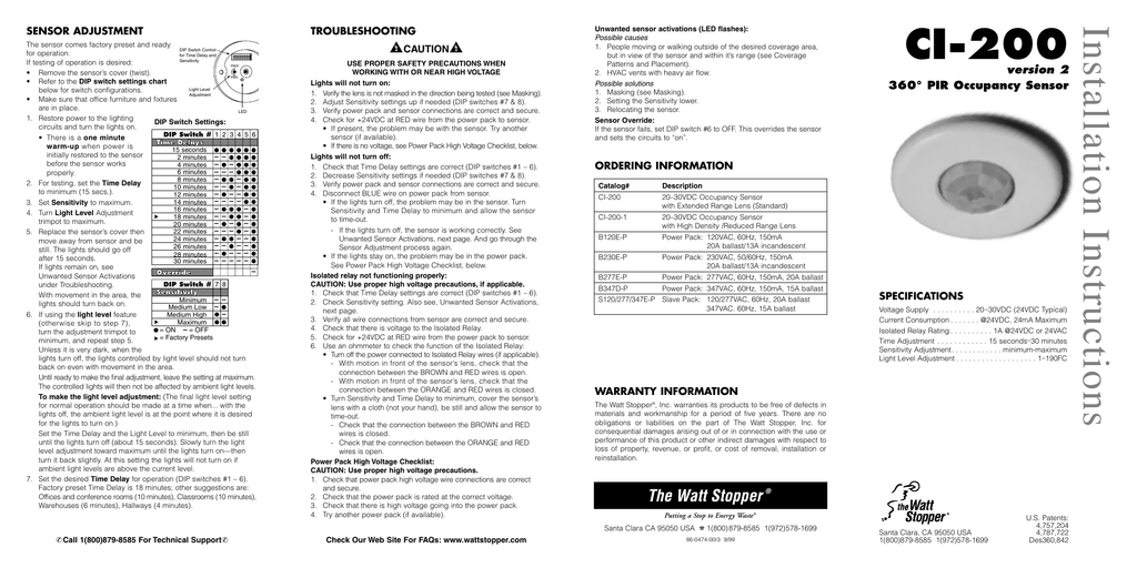
Ci200 Instructions

Watt Stopper Wiring Diagrams Giant Repeat4 Klictravel Nl

Yn 2054 Power To Light Switch Diagram Free Image About Wiring

Wattstopper Digital Lighting Management Dlm

Wattstopper Wiring Diagrams Kuiyt Fuse19 Klictravel Nl
Legrand Wattstopper Dsw 301 User Manual Pdf Download Manualslib
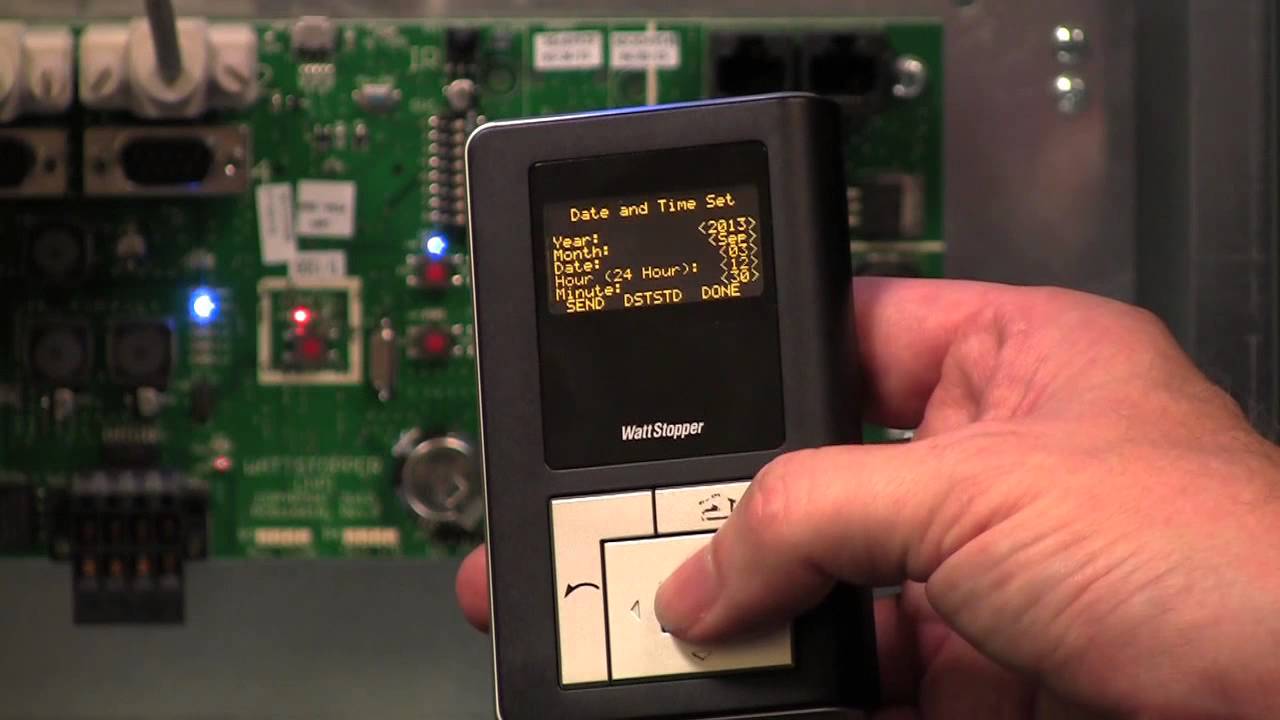
Wattstopper Configuring The Lmcp Part 1 Youtube
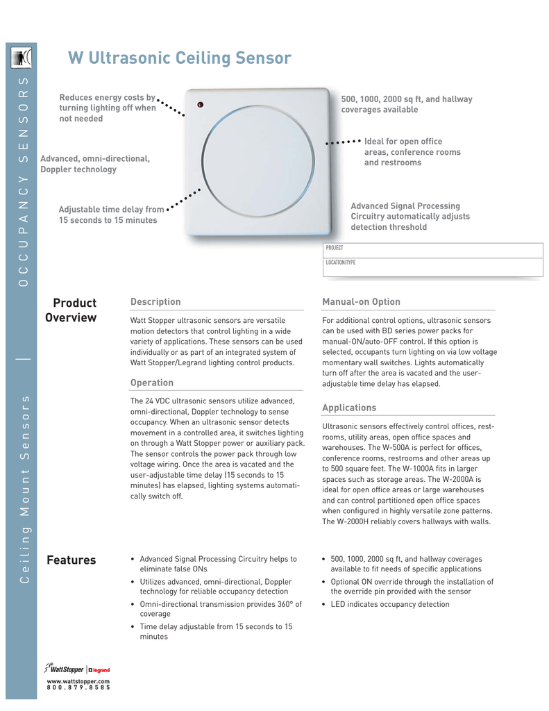
W Ultrasonic Ceiling Sensor
Wattstopper Legrand Pw100w Spec Sheet
Light Control Solutions For Daylit Spaces
